


|
|
|
|
|
|
|
|
SMALL APERTURE TELESCOPE AUGMENTATION STUDYR. Lambour, E. Pearce, S. Ferner, E. Rork, P. Trujillo, A. Decew, P. HopmanMIT Lincoln Laboratory, 244 Wood St. Lexington, MA, 02420 USA
1. INTRODUCTIONGround-based optical sensors are routinely used in the United States and other nations to track
man-made objects (satellites) in deep space orbits due to their inherent advantage in
sensitivity over radars for this task. The United States utilizes the Ground-Based Electro-
Optic Space Surveillance (GEODSS) network for this task. The GEODSS network consists
of three sites distributed globally, each of which has 3 1-m aperture telescopes. These sites
are located at Socorro, New Mexico, Maui, Hawaii, and Diego Garcia. A fourth dedicated
space surveillance site exists in Moron, Spain with a single smaller telescope system (0.56-m
aperture) referred to as the Moron Optical Space Surveillance (MOSS) system. All of these
sites track low earth orbit and deep space satellites obtaining metric and photometric space
surveillance data. Being ground-based sensors, all are subjected to the variations of
atmospheric weather, which can result in the inability to track objects as often as desired,
which in turn can lead to difficulty re-acquiring the objects at a later date. The four sensor
sites are distributed in a roughly uniform fashion longitudinally, so that poor weather can
render a significant fraction of the geosynchronous belt unobservable for one or more nights
at a time. One relatively simple solution to reduce the susceptibility of ground-based sensors
to weather is to increase the number of sensors and disperse them geographically to reduce
the probability that all sensors will be weathered out simultaneously. This concept is referred
to as geographic dispersion.
To address the utility of this concept, MIT Lincoln Laboratory (MIT/LL) was tasked to
formulate broad system-level requirements for a low cost, sustainable, small-aperture, and
autonomous telescope system that could be used cooperatively with the GEODSS network.
This sensor is referred to as the SATA sensor throughout this paper. The goal of the study
was to produce the following products. First, system level requirements and supporting technical analysis were developed for the functional capabilities of the SATA sensor (e.g.,
required sensitivity and surveillance rate). Second, broad concepts for system operations,
maintenance, security, and communications were developed and are presented. We were
instructed not to consider specific sites in detail, so a high-level examination of site
requirements was conducted. These system-level requirements and system concepts were
flowed down to develop derived requirements on some sensor subsystems. Finally, a notional
system design that meets the system-level design and performance expectations was
developed after conducting an analysis of the current state of the market in commercial off-
the-shelf (COTS) system components and an analysis of the current state of the art in the
various system components. Some of the more interesting study products will be described in
this paper.
2. SATA SENSOR OPERATIONAL CONCEPTThe study process began with development of an operational concept for the SATA sensor.
That concept is that the SATA sensor will be a search-based system rather than a traditional
task-and-track system, but will be capable of limited task/track operations and will be capable
of interfacing with the command and control system for GEODSS as well as independent
operation. The primary reason for this concept is the desire not to have to command the
sensors remotely unless absolutely necessary; thereby simplifying routine sensor operations
and reducing sensor operational costs. The primary mission of the SATA system will be to
augment current GEODSS deep space surveillance capabilities by assuming the catalog
maintenance task from the GEODSS system. The SATA sensor(s) is envisioned to operate
autonomously, without need of a human operator or human intervention during normal
operations. We interpret this operational concept as a definition of mission requirements.
Given this operational concept, we have developed system level performance
requirements for the SATA sensor within the context of the current GEODSS network and
with expectations that space-based space surveillance sensors will be deployed in the future.
Our performance requirements are also consistent with the realization that the SATA sensor
will be primarily a search sensor, not a task-and-track sensor. We have utilized forward-
looking operational, maintenance, and force structure concepts in the development of the
system requirements, in particular: 1.) Geographical dispersion to minimize weather outages,
2.) Autonomous, unattended operation, 3.) Streamlined acquisition and maintenance, and 4.)
Use of Commercial Off The Shelf (COTS) components to lower costs if appropriate; COTS
was used as a means and not an end in the sensor design. We have analyzed the design trade
space and have developed a conceptual sensor design as a benchmark for sensor performance
evaluation and cost estimation.
3. SATA REQUIREMENTS DEFINITION AND SUPPORTING ANALYSISAs mentioned previously, the SATA sensor is envisioned to be an autonomous search sensor that will assume the GEODSS catalog maintenance task. Therefore SATA must be able to
detect deep space (DS) targets over its entire field of regard (FOR) throughout any dark
period. This concept, and the brightness of the DS targets it must catalog will be the primary
drivers for the requirements definition.
We propose a set of functional requirements for the sensor based on our operational
concept. These functional requirements in turn flow down and specify a set of derived
requirements that more completely specify the sensor requirements. These functional
requirements are listed and defined in Table 1. Representative derived requirements are listed in Table 2. In the following subsections, we identify the issues impacting the system design
and requirements definition; define each requirement and present supporting analysis for the
definition.
Table 1. Functional Requirements for the SATA Sensor
Table 2. Representative Derived Requirements for the SATA Sensor
3.1 Surveillance Rate RequirementThe surveillance rate (search rate) of an electro-optic sensor and its limiting sensitivity are
interdependent quantities. The surveillance rate of an electro-optic sensor can be defined
simply as:
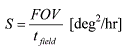 where FOV is the field of view of the sensor in deg2, and tfield is the amount of time spent taking data in a single field. The amount of time spent taking data in a single field depends on the number and length of the exposures, as well as other factors such as the length of time to
actuate a shutter, and the time needed to slew to the next field of interest.
The mission of the SATA sensor is catalog maintenance via search operations; therefore
we assume the sensor is intended to find as many DS objects as possible. Using the sensor to
search regions of the sky with high object density facilitates the mission. Figure 1 illustrates
and defines those high-density regions. The figure shows that two regions, the
geosynchronous belt (GEO belt) and the Molniya apogee region (Molniya ring) present a
large number of potential targets for a ground-based sensor. We use surveillance of those
regions as a metric for developing system surveillance rate requirements. The orbits of other
DS objects must cross the equatorial plane at some point; therefore if surveillance region
covers enough area, the other deep space objects can be detected during GEO belt
surveillance operations.
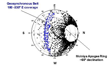 Fig. 1. Location of deep space population as seen from a mid-latitude, northern-
hemisphere site. The GEO belt is represented by the solid line, and is labeled
with east longitude. The circles represent the instantaneous positions of the
visible GEO belt objects. The black squares represent the positions of Molniya
objects at 30-minute intervals over the course of a 24-hour period.
A single sweep of the full GEO belt and the Molniya ring once per evening requires a
surveillance rate of 760 deg2/hour (for the stressing case of a 7.7 hour dark period). When
weather is considered, the actual available time to perform the sweep can decrease, requiring
an increase in sensor search rate to accomplish the mission in a single night. In addition,
previous work suggests that multiple, rapid sweeps of a search area reduces object leakage
through the search area [1]. Minimizing object leakage is a useful goal for the SATA sensor
as it reduces the number of routine objects that would be tasked to the GEODSS sensors, and
facilitates the SATA catalog maintenance mission requirement. If we assume two repetitions
of the search area mentioned previously, and that the weather is clear only 50% of the time,
the surveillance rate requirement increases to > 3120 deg2/hour. Note that data collection during partly cloudy weather could reduce this rate requirement somewhat by allowing a
longer period of data collection. Also note that a sensor placed in the southern hemisphere
would not be able to observe the Molniya ring and could perform it’s mission with a lower
surveillance rate. However, requiring the sensor to perform initial orbit determination (IOD)
on previously uncatalogued objects potentially increases the surveillance rate requirement due
to the need for at least 3 observations of the object [2]. We have proposed the following
requirement: Each SATA site should be capable of sidereal-track surveillance rates
approaching or exceeding 3500 deg2/hour. The objective rate should meet or exceed that
needed to support IOD on previously uncatalogued objects (>4700 deg2/hr).
3.2 Sensitivity RequirementThe sensitivity requirement defines the faintest target that the sensor should be capable of
detecting. Determining this parameter requires understanding the brightness of deep space
targets as well as the impact of noise sources such as the sky brightness and camera/CCD
noise on the overall signal to noise ratio. The SATA sensor is envisioned to operate
autonomously searching large portions of the sky in sidereal-stare mode meaning that objects
will not be scheduled for observations at times when phase angles are low, and conditions
favor them being bright and easily detected. Instead, the sensor will have to detect targets at
unfavorable phase angles, in unfavorable sky conditions (e.g., when the moon is up), and in
unfavorable sky locations (e.g., close to the horizon) during routine operations.
Given these constraints, we note that previously published observations suggest that
large geosynchronous satellites easily reach exoatmospheric absolute magnitudes as faint as
~15 at large phase angles (~80° - 90°) and distances of 36,000 km [3]. Slant ranges can be >
36,000 km, meaning that the observed apparent magnitude can be fainter. Atmospheric
extinction further reduces the apparent magnitude by approximately 0.2 – 0.6 magnitudes
depending on the zenith angle of the observation. We have concluded that the SATA sensor
should be required to observe targets down to an apparent magnitude of 16 at all elevations
greater than 20°.
The magnitude of the sky background varies considerably from site to site, and also
varies spatially and temporally due to airglow and the presence of the moon. It also varies
with the phase of the moon and the relative position of the moon and the field of observation
of the telescope. We have constructed a semi-empirical model of sky brightness from
modeling results of [4, 5] and adapted them for wide CCD sensor bandwidths. Our model
suggests that the sky background along the GEO belt and Molniya ring regions is fainter than
18 mag/arcsec2 more than 85% of the time over the course of a year. The model results are
shown as cumulative distributions in Figure 2 for two airglow cases. Therefore, we suggest
the following sensitivity requirement for the SATA sensor: it should be able to detect a target
with an apparent magnitude of 16 in a sky background of 18 mag/arcsec2. The sensor
should perform at this specification at all elevations down to 20°. This requirement provides
a robust system capable of operating in realistic sky background conditions and at most
elevations.
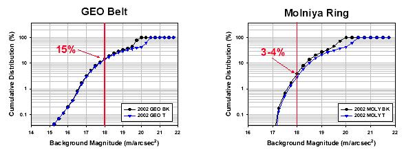 Fig. 2. Cumulative distribution of sky brightness for the geosynchronous belt (left) and
the Molniya ring (right) as observed from a mid-latitude, northern hemisphere
site. The circles denote the severe airglow case (BK) [6], and the triangles denote
the typical airglow case (T) [7].
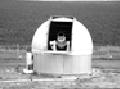
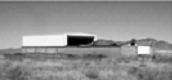
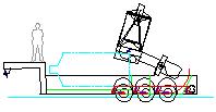
3.3 Telescope Enclosure, Deployment Options, and Transportation RequirementsThis section briefly discusses the functional requirements on the SATA telescope enclosure,
as well as deployment options and transportation requirements. Some of these requirements
impact development of site requirements. Our overarching goal in the development of
enclosure and siting requirements was to minimize the amount of site preparation needed for
the SATA sensors, thereby reducing the time and cost needed to deploy the sensor. Benefits
and drawbacks of several telescope enclosure options are summarized in Figure 3. Our
recommendation for the SATA sensor is an integrated transporter/shelter (ITS). This option
requires relatively little site preparation relative to the dome or rolling roof enclosures, and it
supports a highly streamlined depot-centric deployment, maintenance, and sustainment
concept. It also facilitates rapid redeployment of the sensor to mitigate seasonal weather
outages. The integrated transporter/shelter would be a custom design for the SATA sensor,
however, several vendors have already designed and built trailer-mounted telescopes, and the
cost is not anticipated to be significantly different from the dome or rolling roof options [8].
This concept increases tactical utility of the SATA sensors and has a lower life cycle cost than
the traditional deployment options of dome or rolling roof enclosures.
Fig. 3. Telescope enclosure option summary
The depot-centric deploy and retrive deployment concept minimizes requirements on
the SATA site. Simple requirements are for a modest concrete pad, local power and
communications, a security perimeter, and relatively good astroclimactic conditions (seeing,
night sky brightness). The autonomous nature of the sensor also requires integration of
weather sensors and remote interrogation of sensor health and status. In addition, we
recommend that a cloud monitoring scheme or sensor be used at the site to increase the
overall utility of the sensor by facilitating operation on partly cloudy nights.
3.4 Derived System RequirementsThe surveillance and sensitivity functional requirements detailed in the previous sections flow
down to derived requirements for the telescope optics, the CCD camera, and the telescope
mount. The high surveillance rate requirement (Section 3.1) immediately suggests that a
wide-FOV telescope is needed (along with a rapid readout CCD camera). The wide FOV in
turn suggests that the telescope should have a low focal ratio or f-number (f/#). In order to
make full use of the wide FOV at the desired sensitivity, the optics must also have good off-
axis image quality, that is, the system must be relatively free of aberrations over the entire
FOV and the optics should have minimal vignetting.
With regard to the required aperture size, we present Figure 4, which demonstrates the
tradeoffs between surveillance rate and limiting sensitivity as a function of telescope aperture.
Figure 4 assumes use of the CCD camera properties listed in Table 4. Other assumptions
include:
1.) a constant focal ratio of f/1.5, 2.) a sky brightness of 18 mag/arcsec2, 3.) a target angular rate of 15 arcsec/sec for the sidereal track case, typical of geosynchronous targets, 4.) atmospheric extinction of 0.6 magnitudes (equivalent to a sensor elevation of about 20°), 5.) limiting magnitude is calculated for an SNR of 6, and 6.) atmospheric seeing of 2 arcsec. Therefore Figure 4 suggests the telescope aperture necessary to satisfy the requirements developed in Section 3.1. A sensor capable of satisfying the requirements would have an aperture in the 50-60-cm range. A smaller aperture has a high surveillance rate but insufficient sensitivity, whereas a larger aperture has sufficient sensitivity but insufficient surveillance rate. 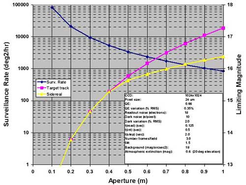 Fig. 4. Comparison of surveillance rate and limiting sensitivity as a function of telescope
aperture for an f/1.5 telescope with a specific CCD camera. For the sidereal track
case, we have assumed a target angular velocity of 15 arcsec/sec. The remaining
assumptions are detailed in the box.
The surveillance rate and sensitivity requirements developed for the SATA sensor
suggest that high quantum efficiency, low-noise, large format, and fast readout are the
desirable requirements for the CCD camera. The pixel size is a secondary requirement, but
must also be considered, as it impacts sensitivity and overall metric accuracy. In general
silicon CCD pixel sizes fall between 10 –30 μm, so a pixel size of ~15 μm with an on chip
binning capability would provide the most flexibility. A comprehensive survey of
commercial CCD cameras was conducted for this study. Most COTS CCD cameras were
designed for astronomical applications and have unacceptably slow readout times. Some
existing CCDs can be read out faster, but with a noise penalty. We did not consider vendors
that produce CCDs with readout times above 10 seconds. We also considered using state of
the art custom CCD cameras such as the 80-mm format CCD camera used for Deep STARE;
however use of that CCD would require expensive custom optics to accommodate the larger
focal plane. Since some existing COTS 42-mm format cameras can provide the required
sensitivity (cf. Section 4), we see no compelling reason to recommend utilization of large-
format, custom, state of the art CCD cameras. We also note that none of the COTS cameras
we surveyed used frame transfer CCDs; therefore a very robust shutter mechanism would also
be needed.
Many commercial vendors offer suitable telescope mounts for ~50-cm class telescopes
for customers ranging from amateur astronomers to military. The mounts vary in quality to
meet user requirements. Space surveillance operations result in more stressing requirements
on the mount than is typically encountered for astronomical or research applications. In
particular, the mounts are frequently required to slew at high rates and operate continuously
over the course of a night. The mounts are also required to step from one location to the next
and damp their motion rapidly. We recommend that the SATA mount be required to step
and settle rapidly, be robust enough for continuous operation over extended periods (up to
~15 hours at a mid-latitude site), be capable of rapidly slewing from one surveillance area
to another, and also be capable of tracking DS targets at typical DS target rates. A quality
university or research grade telescope mount will be suitable for SATA with minor
enhancements to make the mount more robust. The mount could be fitted with oversized
motors and gears, or an “oversized” mount could be used. Note that investment in a high-
quality mount for the SATA sensors can significantly enhance the sensor surveillance rate and
is strongly recommended.
4. NOTIONAL SATA SENSOR DESIGNIn this section we present a notional design for the SATA sensor. The sensor design
discussed in this section covers the optics and CCD camera in detail, but does not represent a
complete design. The principles we adopted in this design were:
1.) It would be based on COTS components wherever possible, 2.) It will utilize open systems computer architecture (i.e., COTS equipment), 3.) It will use the “deploy and retrieve” concept for basing and sustainment described previously, and 4.) The system is focused on providing adequate augmenting capability for the GEODSS network, while minimizing life cycle cost. The design consists of 60-cm class Ritchey telescope with a COTS mount. We present
one compact optical design that achieves excellent image quality and can support CCD
cameras with pixel sizes down to ~12 μm. The design uses custom, but relatively inexpensive
and readily manufactured optical components to accommodate the wide FOV necessary for
surveillance. However, any 60 cm class telescope is “custom” built by a telescope
manufacturer; they do not exist as COTS units. A COTS 40-mm format CCD camera is
recommended as the imager. Use of a COTS product ensures availability, and the 40-mm
focal plane format does not strongly drive the cost of the optics. The system must also have control computers and image processing software. We assume the system uses an integrated
trailer and shelter enclosure, as described in Section 3, although we have not designed such an
enclosure for the notional sensor; this design would be left up to future bidders. In other
respects we assume that the sensor will fulfill the requirements outlined in Section 3.
The design is a 60-cm aperture f/1.25 Ritchey design. Figure 5 presents a ray trace of
this system. There are two hyperbolic mirrors and two aspherical corrector lenses. The
secondary mirror represents a modest central obstruction (25% of the aperture area). The
design is corrected for chromatic aberrations over the wavelength range of 400 – 900 nm.
Figure 6 presents the accompanying spot diagram for this design. The design has excellent
image quality out to the edge of the focal plane, and can support the use of a CCD camera
with ~12 μm pixels.
A commercial CCD camera with a 40-mm format focal plane is recommended. A
specific vendor is not recommended, but we have used properties of a commercial camera that
has rapid readout and is back-illuminated (cf. Table 4).
We assume the computer hardware and software required by the SATA sensor will be
similar to that in use at the Moron Optical Surveillance System. The relevant MOSS
computer hardware would involve several LINUX-based PCs including an executive control
computer to manage the overall sequencing of telescope operations, communications, and
interrogation of the weather sensor control computer. Other computers would handle
telescope mount control, scheduling of observations, image processing and object correlation,
and data storage.
The software system at MOSS is roughly 80-100K lines of source code (SLOC)
developed specifically for the space surveillance mission. We strongly suggest that software
for the SATA sensors be developed for its surveillance mission and in parallel with the SATA
hardware development and integration, reusing code from existing systems when possible.
We recommend against the strategy of utilizing COTS software components integrated with
custom software patches. We believe this COTS-only strategy will complicate maintenance
and sustainment of the software, as the COTS vendors will be under no obligation to sustain
software or customize software needed for the system.
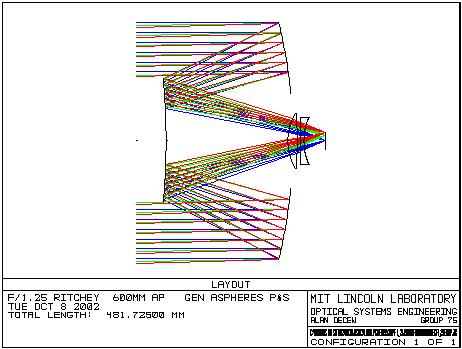 Fig. 5. Optical layout of optical design for the SATA sensor.
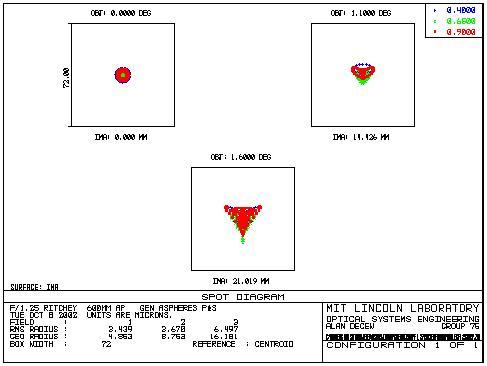 Fig. 6. Spot diagrams for the SATA sensor.
4.1 Notional Sensor PerformanceWe examine the performance of the SATA sensor design, and estimate its capability for
meeting functional and mission requirements defined in preceding sections. In order to
estimate sensor performance, we have had to make assumptions regarding the type of CCD
camera in use, the performance of the telescope mount, and the performance of the image
processing software. Those properties are listed in Table 4.
Table 4. Assumptions Made in Modeling of Notional Sensor Performance
[b] Aggressive assumption. [c] Recommend seeing at SATA sites of this quality or better. The estimated limiting magnitude (i.e., sensitivity) at SNR=6 is presented as a function
of integration time in Figure 7. The figure presents limiting magnitude vs. integration time
for targets with various apparent motions across the focal plane. The target rate of 15
arcsec/sec would be representative of a geosynchronous object; Molniya objects would move
at slower rates near apogee (<5 arcsec/sec). The figure assumes the sensor is pointed at 20°
elevation and an atmospheric extinction of 0.6 magnitudes has been applied. We have also
assumed a sky background of 18 mag/arcsec2, which is fairly bright, but consistent with the
sensitivity requirements. This sensor achieves a limiting magnitude of 15.85 for a GEO
object at an integration time of ~0.4 seconds. At zenith, the sensor achieves a limiting
magnitude of 16.25. This sensor meets the 16th magnitude requirement for SATA at zenith
and is slightly short of the requirement at 20° elevation; there is no margin in the sensor under
those stressing conditions. The sensor performance is improved under darker sky conditions.
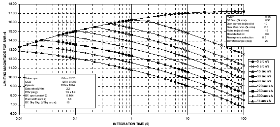 Fig. 7. Limiting magnitude of 0.6-m f/1.25 SATA sensor with camera properties as listed
in Table 4 for various integration times and target angular rates. A sensor
elevation of 20° was assumed.
A statistical examination of sensor performance is presented in Figure 8. The figure
presents the fraction cases that the sensor limiting magnitude was greater than a certain value.
The estimates were made using the sky background model output along the GEO belt and the
Molniya ring as described previously (cf. Figure 2). We used those sky background estimates
to facilitate estimation of the sensor limiting magnitude at multiple points along the arcs of
interest, including the effects of atmospheric extinction and assuming a target SNR=6 for
detection. Therefore Figure 8 represents limiting magnitude statistics along the GEO belt and
Molniya ring over the course of a year. The realized limiting magnitude is dependent upon
how the sensor is used; to derive the statistics, we assumed an integration time of 0.3 seconds
and an apparent angular rate of 15 arcsec/sec for the GEO belt and 5 arcsec/sec for the
Molniya ring. This presents a single performance point in a large parameter space. We also
assume clear weather for the year. Each plot presents results for the two known airglow cases
(typical and severe). Approximately 91% of the GEO belt cases examined have limiting
magnitudes > 16, and 98.5 – 99% of the Molniya ring cases have limiting magnitudes > 16.
These results demonstrate that in general, this sensor meets the sensitivity requirements in >
90% of the cases examined, and may fall slightly short (0.1-0.15 magnitudes) of meeting the
requirement in the extreme case of low elevation and a very bright sky background.
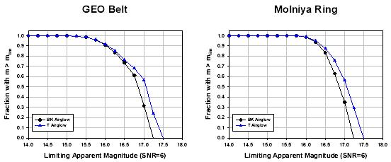 Fig. 8. Sensitivity statistics for the 0.6-m f/1.25 SATA sensor. (Left) Sensitivity along
the GEO belt. (Right) Sensitivity along the Molniya ring. All calculations are for
a mid-latitude, northern hemisphere observing site.
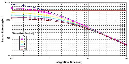 Fig. 9. Estimated surveillance capability of the notional SATA sensor as a function of
integration time and step and settle time. The horizontal line indicates the
surveillance requirement from Section 3.1.
This sensor concept has a FOV of 1.9° x 1.9°. Figure 9 presents estimated surveillance
rates for a single sensor using the assumptions listed in Table 4 (with the exception that we
have plotted the search rate for multiple sensor step and settle times). The horizontal line
indicates the surveillance requirement outlined in Section 3.1 (3500 deg2/hr). Within the
likely operational envelope of tint = 0.3 – 1.0 seconds, this system meets the requirement at tint < 0.5 sec and falls below it for larger values of tint. Even so, at tint = 1.0 seconds, the surveillance rate is still at 2415 deg2/hr.
5. CONCLUSIONSMIT/LL has developed broad system-level functional requirements for a sustainable, small-
aperture, low-cost, and autonomous telescope system envisioned to augment the current deep
space electro-optical (EO) network. These requirements have been developed within the
context of the current EO network (i.e., GEODSS with the Deep STARE upgrade) and the
expectation of future Space-Based Space Surveillance deployment. We have assumed that
the SATA system will be a surveillance-based system rather than a task/track system, but that
the system must also be capable of limited task/track capability. We have assumed that the
SATA sensors will augment the GEODSS system by adding capacity and assuming the
catalog maintenance task from the GEODSS system. We have focused on developing a
sensor with significant surveillance capability to minimize the number of objects that leak
through the EO surveillance fences.
The functional requirements have been listed in Section 3 and throughout this report.
These requirements flow down to set derived requirements for the sensor. We envision the
SATA sensor to consist of a ~60-cm aperture, wide field of view (FOV) telescope (F/1.5 or
below), a commercial 42-mm format CCD camera with high quantum efficiency and rapid
readout, and a robust research grade equatorial fork mount capable of the continuous
operations required by the space surveillance mission. We recommend that this sensor system
be housed in an integrated transporter and shelter to facilitate a streamlined maintenance
concept and also rapid redeployment, if desired. The system is envisioned to be autonomous
and thus requires an autonomous control computer system tied to robust weather sensors, and
local power and communications.
A notional sensor design was developed as a performance benchmark. The notional
sensor is a 0.6-m aperture f/1.25 system with a COTS 42-mm format CCD camera. Tools
were developed to estimate the performance of this sensor under realistic sky background
conditions, including the effects of scattered moonlight and airglow. The analysis suggests
the notional design is capable of meeting it’s sensitivity requirement in more than 90% of the
sky background conditions that exist over the course of a year. Four sensors, distributed
geographically, would provide sufficient coverage of deep space to perform routine catalog
maintenance and provide augmentation of the GEODSS sensors.
Acknowledgements. This work was sponsored by the Department of Defense under Air Force Contract No. FA8721-05-C-0002. Opinions, interpretations, conclusions and recommendations are
those of the author and are not necessarily endorsed by the United States Government.
REFERENCES
Размещен 29 ноября 2006.
|
|
|
|
|
|
|
|
|