


|
|
|
|
|
|
|
|
OPTICAL OBSERVATIONS IN A PROPOSED EUROPEAN SPACE SURVEILLANCE NETWORKT. Schildknecht, T. Flohrer, R. MusciAstronomical Institute, University of Bern, CH-3012 Bern, Switzerland
1. INTRODUCTIONToday, the number of satellites and the number of space debris objects is still growing. The
end-to-end monitoring of space activities is essential for the success of present and future
space missions. The task of space surveillance, combining the detection, tracking,
identification, and cataloguing of artificial objects in space, is an integral part of space activity
monitoring. Space surveillance was and is driven by military and governmental needs, but
civil entities are becoming important drivers, too. Typical applications of a space surveillance
system are in the field of space traffic management (as manoeuvre identification and
assessment), fragmentation detection, re-entry prediction and monitoring, pre-launch
assessment, and verification of compliance with space regulation treaties and
recommendations.
Currently, a limited number of European radar and optical facilities perform space
surveillance tasks, but there is no existing operational European space surveillance system.
The various European commercial and scientific space activities are strongly dependent on
external data in terms of space surveillance.
In the years 2002 – 2004 a study team led by ONERA (Office National d’Etudes et de
Recherches Aerospatiales) conducted an ESA-funded feasibility study for a future
independent European space surveillance capability. Alcatel Space, QinetiQ, and the Astronomical Institute of the University of Berne (AIUB) participated in this study. The study
focussed on space surveillance in the Low-Earth Orbit (LEO) and in the GEO region. With
considered minimum object diameters of catalogued objects of 10 cm in LEO and 1 m in
GEO, the system is required to perform similar to the U.S. or Russian space surveillance
networks. Contrary to the existing networks, the European system proposal focuses on space
surveillance tasks and does not include additional early warning functions. The final report of
this study is available [3]. An overview over the complete system is also given in two papers
[4], [5].
A still ongoing follow-on study assesses in detail the system, taking also a closer look at
objects in Medium Earth Orbit (MEO) and at objects in highly elliptical orbits (HEO). The
study team is again led by ONERA. AIUB is responsible for the optical part of the detailed
assessment. This study will be completed in autumn 2005.
Two sensor types were selected: ground-based telescopes equipped with CCD cameras
shall cover the GEO and MEO region. Phased array radar sensors (like the French GRAVES
system) will survey the LEO region. This paper will present the results from AIUB’s work on
the optical part of the proposal - the development of observation strategies, the selection of
optical detectors and sensor architecture, and on the performance estimation of the proposed
system.
In this paper we will address the space surveillance of the GEO and MEO region by
optical sensors in individual sections ([2] and [3]). Both include the presentation of the
selected observation strategy, the outline of the sensor architecture and network, and the
estimated performance of sensor and population coverage. A section dealing with the
validation of cataloguing algorithms that is applicable to both, GEO and MEO, is added
(section [4]). This paper ends with a conclusion and outlook to the next steps.
2 CONCEPT FOR GEO SPACE SURVEILLANCEIt is assumed that GEO space surveillance needs to consider all objects larger than 1 m in
diameter that orbit the Earth at 35768 km +/- 2000 km altitude in near circular orbits with
inclinations below 17°. This is a common definition of the GEO population.
2.1 GEO observation strategyThe proposed approach for GEO space surveillance is twofold, combining survey and tasking
observations. Survey denotes the task of searching for so-far uncatalogued (new) objects. This
also includes the search for lost, previously catalogued objects, the sometimes also called ‘no-
shows’. Tasking, on the other hand, stands for all scheduled observations carried out on-
request. Tasking observations comprise the routine observations needed to ‘secure’ the
catalogued objects (catalogue maintenance), and the special task observations. Special task
observations are needed for orbit improvement of newly detected objects prior to catalogue
correlation, for manoeuvre assessment, detection of fragmentation events and conjunction
analysis, for searching for lost objects with specific patterns, among other tasks.
2.1.1 Survey strategy The survey strategy is presented in detail in [6]. In brief, the survey strategy assumes that all
objects in the GEO will appear under a given right ascension once in about 24 h, as the mean
motion of GEO objects is about 1 rev/day. If survey sensor observations cover the declination
range between -17° and +17° of a fixed right ascension continuously, within 24 hours the
entire GEO is surveyed. A single site cannot observe this (so-called) stripe for 24 h, but a network of sites can. In such a network, the observed stripe is ‘handed over’ from one site to
the next site westwards, requiring that there are no coverage gaps in the network.
The right ascension of the observed stripe is selected nearly opposite to the Sun, close to
the Earth’s shadow. This allows observation under optimal phase angle conditions. Of course,
the right ascension of the stripe will undergo a change of about 1°/day during the year due to
the revolution of the Earth around the Sun.
Further it is assumed, that it is sufficient to observe each GEO object at least once every
15 days, depending on the required orbit accuracy [8]. The stripe may therefore be divided
into equally sized fields. This relaxes the sensor requirements in terms of covered survey area,
as the size of an individual field corresponds to the field of view (FOV) of the telescopes.
Each of the fields has to be observed for 24 uninterrupted hours once within 15 days so that
nearly all objects in the GEO ring will be observed at least once within 15 days.
In order to be able to determine orbits from the survey we need to acquire a sequence of
exposures. From experience, three to six observations of a particular object are sufficient to
determine a first orbit and to prevent wrong correlations or even false detections caused by
cosmic ray events. As the GEO objects cross the FOV in a (comparatively) uniform manner,
‘blind’ tracking during the exposure can be applied to improve the object signal at the
detector. If the FOV of the sensor is wide enough so that the FOV dwell time of the GEO
objects leaves some spare time, another (neighbouring) field may be observed in parallel. This
in turn reduces the total ‘stripe scanning’ time and better allows compensating for sensor
unavailability. If the FOV of the telescope is, however, not wide enough, it is mandatory to
observe more fields in parallel to fulfil the 15 days stripe scanning time limit. To cover
objects crossing the FOV close to the field border sufficiently, neighbouring fields should
slightly overlap.
2.1.2 Tasking strategy Most of the tasked observations will be scheduled to provide the observations of newly
detected objects at defined epochs to determine ‘secured’ orbits. The request for a tasked
observation consists of the position (right ascension and declination of an object) at a specific
epoch. Therefore, the tasking strategy is simple and straightforward: the telescope tracks the
ephemeris of the object and the exposures are acquired following the requested pattern.
The tasking strategy allows observing more than one object ‘in parallel’, if possible. It
needs to be noted that the angular distance between objects observed ‘in-parallel’ may be
limited by the tasking telescope slew rates and settling times.
2.2 GEO sensor architectureThe presented observation strategy requires dedicated survey and tasking telescopes. Both
must be arranged in a network guaranteeing a permanent accessibility of the entire GEO. Both
sensor types must allow the detection of objects with 1 m diameter. For the following
considerations, the decision criteria for the detection of a so-called ‘crossing object’ (an object
crossing the telescope FOV), is the signal to noise ratio (SNR). The sensor architecture must
ensure that the SNR of crossing objects under normal observation conditions is always above
a given threshold. In this case we consider the crossing objects as being detected by the
sensor, all other objects are treated as undetected. For the SNR estimation we used an
approach similar to the one described in [12].
2.2.1 Sensor parameters The study [3] concluded that for both, survey and tasking, a 0.5 m diameter Schmidt-
Cassegrain f/2 telescope equipped with a 2k*2k back-illuminated CCD performs best. The
pixel scale (PS) of this system is 5.27 ”/pixel, leading to 3° FOV diameter. See Figure 1 for an
estimation of the SNR at the detector as a function of the background brightness. The
assigned object diameter (in meters) is calculated for a geometric albedo of 0.1 and a phase
angle of 0°. It is assumed that the objects move with a velocity of 5 ”/s with respect to the
FOV, and that the exposure time is 2 s. For the detector a peak quantum efficiency of 0.9 was
assumed, signal loss due to the atmosphere and the optical system is considered. Typical
detector noise values of commercially available detectors were assumed.
The performance of the proposed sensor is sky background signal limited due to the
selected pixel scale and exposure time. The background signal is not constant, as the
background magnitude is a function of the appearance and the phase of the Moon, the star
background density, the general observation site quality, and the local atmospheric seeing
conditions. We have to ensure that even under bad conditions, the sensor design allows for the
observation of objects of 1 m diameter. Under optimal conditions, a ground-based sensor may
be operated with background signals of less than 19.5 mag/arcs2, while sites close to urban
areas only rarely have a background fainter than 17 mag/arcs2. If we assume a conservative
SNR detection threshold of 4, we conclude from Figure 1 that with the proposed 0.5 m sensor,
the detection of 1 m objects in the GEO region is always possible. Concerning the detection
of smaller objects or considering the use of a narrower aperture, we have to bear in mind that
the plot is for an optimistic case. For the tasking sensor the zero phase angle assumption is
only rarely fulfilled, while for the survey sensors the velocity of FOV crossing objects is
higher, with about 15”/s. As a result only a lowered SNR will be achievable and, thus, the
detection of 80 cm objects cannot always be guaranteed, as the plot may suggest.
We will show an additional assessment of the minimal detectable diameter in the next
section dealing with the GEO space surveillance performance.
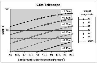 Fig. 1. SNR for GEO objects of various magnitudes as function of background magnitude.
2.2.2 Network for survey and tasking The analysis of the visibility of GEO objects from particular sites showed that for a minimum
elevation angle of 20° and for typical GEO distances, an arc of about 125° in longitude is
accessible from a near-equator site. Thus, to have some overlap and to use sites at low
latitudes promising better weather conditions and accessibility, at least 3 low latitude sites are
needed to cover the entire belt of GEO objects around the Earth continuously and almost completely. The study [3] selected four potential sites where the GEO sensors could be
installed in order to guarantee some overlap and redundancy: Tenerife (Canary Islands,
Spain), Cyprus (Mediterranean Sea), Perth (Western Australia) and the Marquesas Islands
(French Polynesia).
Figure 2 shows the proposed GEO space surveillance network configuration and the
coverage of the GEO. The network covers the GEO region sufficiently well. A prominent gap
around 45° East is closed by the introduction of the Cyprus site. A smaller gap around
40° West remains.
The study proposes that each site of the network is equipped with at least two identical
telescopes, one for the survey and one for the tasking. The use of identical sensor
architectures promises a reduction of the network complexity and cost benefits. Additional
telescopes may provide some redundancy and reduce the risk of observing site outage.
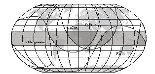 Fig. 2. Coverage of the GEO region (grey band) by the proposed space surveillance network. The lines indicate regions where objects at GEO distances are observable from a particular site under 20° elevation.
2.3 GEO performance estimationUsing the preliminary sensor architecture from the previous section, we discuss the
performance of the GEO system proposal in terms of coverage of a reference population and
in terms of minimum diameter of detectable objects. For both steps we use the ESA PROOF
tool (Program for Radar and Optical Observation Forecasting), in the version 2001. PROOF is
a tool for debris model validation and observation forecasting [7]. With this tool, observations
from radar and optical sensor can be simulated for both, ground-based and space-based
applications. PROOF makes use of ESA’s MASTER reference population of uncatalogued
objects [1].
We will only consider the performance of the survey strategy here. The tasking strategy
performance was addressed in detail in [6]. There we concluded that for a catalogue of 1500
objects, the necessary tasking observations could be carried out with the proposed system. If
the tasking sensors provide a high telescope slew rate above 5 °/s, it is proposed to observe up
to three objects “in parallel”. In this case the remaining telescope time of up to 70% of the
total observation time can be used to support the survey system, or for other purposes such as
tasking of MEO objects.
2.3.1 Coverage of reference population We implicitly assume that the coverage of an existing and known population of objects by the
survey strategy is valid for the discussion of the general survey performance. The PROOF
tool was used to simulate observations scheduled according to the proposed survey strategy.
The ESA DISCOS TLE catalogue provided a reference population of 793 objects. The
simulation covers one complete survey cycle in December 2003 and considers two cases: 8 h observation time per site and day and 12 h observation time per site and day. However, 12 h
of survey are not always possible throughout the year. The observation of two fields observed
in parallel was simulated - it would take 8 days to cover the entire declination stripe in this
case. These 8 days are, therefore, the repetition rate of the survey observations for particular
objects.
The analysis was carried out for each survey sensor site individually and later all results
were combined. The combined results for the proposed system architecture are contained in
Table 1. The term ‘Uniques’ denotes objects that cross the FOV only once within the
simulation period or once detected. ‘Doubles’ refers to objects that cross the FOV at least
twice or were detected multiple times. 95% to 99% of the reference population crossed the
FOV of the sensor network, proving that the survey strategy is sufficient.
When excluding the fast drifting objects (drifting faster than 5 °/day), an analysis of the
longitude distribution of the missed objects shows the mentioned small coverage gaps at
40°W [6]. The tabulated results also show that some objects (about 5% of the crossing
objects) cross the FOV undetected. Mostly, the bright background conditions during twilight,
while the object crossed the FOV, could be identified as the reason. For very few objects that
were found still bright enough, but remained undetected, the PROOF detection algorithm
failed for unknown reasons. With this strategy, a (peak) crossing rate of 50 objects/hour is
expected. The analysis also confirmed the assumption that objects with diameters larger than
1 m are always observed with magnitudes brighter than 17 mag.
We conclude that the proposed survey strategy is sufficient to be used in the GEO part
of the proposed space surveillance system. It is, however, important to stress that the survey
strategy requires the entire observation time of a single survey sensor. In consequence, there
is no time left to perform tasked observations and there is no redundancy for the survey using
a single dedicated survey telescope per site.
Table 1. Number of unique and double crossings (white columns) and detections (grey
columns) and the coverage of the reference population. Detection algorithm simulated with
PROOF.
2.3.2 Minimum detectable objects size The minimum detectable object diameter can also be assessed with the PROOF tool. The
minimum detectable object diameter is an important parameter for the planning of surveys.
Further, in order to evaluate systems capability to maintain a catalogue of objects above a
required diameter, the minimum detectable object diameter during tasking must be known.
The simulation was limited to objects crossing between 30,000 and 60,000 km altitude and
covered the entire survey cycle starting at two different epochs: a full Moon run, starting
2003-Sep-23, and a new Moon run, starting 2003-Dec-03. For each night during the
simulation period an observation sequence of 8 h was simulated. The simulations were
performed for the Tenerife site. Again, a ‘conservative’ SNR detection threshold of 4 was
used. As no ‘blind’ tracking during the exposures was applied, we expect that improvements
in terms of the minimum detectable object diameter are possible.
The results in Figure 3 for the 0.5 m telescope show that the detection of 1 m GEO
objects is always possible. As a result of the Moon phase, a clear bifurcation is visible in the
plot. The minimum diameter of detectable objects is at 1 m under bad conditions, while under
better conditions objects as small as 50 cm (on some occasions even 30 cm) are detected.
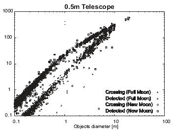 Fig. 3. SNR of crossing and detected objects vs. object diameter as resulting from simulations using the PROOF tool.
3 CONCEPT FOR MEO SPACE SURVEILLANCENot very much information is published on MEO space surveillance so far, which may
indicate a lower interest in this region. Nevertheless, the availability of orbital elements for
the active and inactive GPS and GLONASS satellites in the USSTRATCOM catalogue shows
that MEO space surveillance is successfully performed for the MEO region. Brief examples
of possible MEO space surveillance strategies were only found in [10].
As no common MEO definition is available, we had to come up with our own definition
for the purpose of this study: MEO combines all objects orbiting the Earth in low eccentric
orbits (e<0.16) with a mean motion between 1.5 and 2.5 revolutions/day and an inclination
below 67°.
As for the GEO, the future European system is required to consider all objects larger
than 1 m in diameter in the MEO region. Contrary to the GEO population, objects in the MEO
may cross the FOV of a sensor with a wider range of possible directions and velocities, as
well as topocentric ranges and phase angles.
A detailed analysis of the existing and future MEO population revealed that the worst
possible phase angle is approximately 120° during nighttime, but phase angles of 0° are
possible, too. Further analysis showed that for the most cases at least one observation of an
particular object per night could be carried out under a phase angle of less than 90°. As
topocentric ranges are typically smaller than 25,000 km (or 29,000 km for Galileo), we may
estimate typical magnitudes (for conservative assumptions for albedo and shape) for the 1 m
objects. We expect 1 m objects in the MEO to appear as bright as 15.5 mag (best illumination
conditions) and brighter than 18 mag (worst illumination conditions at 120° phase angle).
The angular velocities are between 20 and 45 “/s in the azimuth/elevation system, and
between 15 and 40 “/s in the right ascension/declination system when the objects are at low
declination. Therefore, the typical dwell times for a 1° FOV fixed in the inertial space is
5 minutes for low declination (6 min for Galileo) and about 15 minutes at high declinations
(>50-60°).
3.1 MEO observation strategyConsidering the population characteristics, it becomes evident that the GEO strategy is not
applicable for MEO observations, as the allowed sensor gap time in GEO and the high
angular velocities of MEO objects prevent any leak-proof coverage of the MEO region.
The analysis of typical space surveillance cases shows that the MEO space surveillance
strategy needs to provide survey capabilities as well as some tasking capabilities (scheduled
observations of individual objects). Thus, depending on the needed tasking frequencies and
the number of objects, two strategies can be formulated: a pure survey strategy and a
combined survey and tasking strategy. A pure survey strategy is sufficient, if the acquisition
of the necessary tasking observations is guaranteed within the survey observations.
It became clear during the study that it is beneficial to limit the considered survey space,
since for a permanent and complete accessibility of the entire MEO space at least 6
observation sites would be needed.
3.1.1 Survey strategy The proposed approaches of the U.S. network (an eccentric semi-synchronous orbit apogee
search and a circular semi-synchronous orbit search, see [10]) were found to be only partly
suited. For both, an initial catalogue is needed and the MEO region cannot be covered
entirely. As the European Space Surveillance System is required to have a cold-start
capability, and uncatalogued objects shall be searched for, another survey strategy was
developed.
 Fig. 4. Apparent density of (catalogued) MEO objects together with the
“fixed declination stripe” for DE = 0.
A promising survey strategy is based on the fact that MEO objects orbit the Earth with a
mean motion around 2 rev/day. Thus, the continuous and uninterrupted observation of a so-
called ‘fixed declination stripe’ allows a complete survey of the MEO population. Such a
declination stripe denotes a region in the sky defined by the entire right ascension range
(considered as stripe “width”) and the sensor FOV (considered as stripe “height”). In order to
access even objects in low-inclined orbits, a stripe covering the declination of DE=0 deg is
proposed for the survey strategy (see Figure 4). This stripe will be crossed 4 times per day, at
least 2 times under valid phase angle conditions.
Some improvements of this strategy are still possible. In particular, the accessibility of
the whole MEO population under valid illumination conditions is guaranteed from a single
site within a few (about 3) months, as the orientation of the orbital plane with respect to the
direction to the Sun changes only slowly. The change is caused by the revolution of the Earth around the Sun (about 1 °/day) and the significantly smaller motion of the right ascension of
the ascending node of the MEO objects (about 2 '/day). This would theoretically allow using
one survey sensor only for the entire MEO space surveillance survey task. It is, however,
proposed to use two dedicated MEO survey telescopes that are spaced by about 90° in
longitude to cope with objects appearing under very poor illumination conditions or having
longer revolution periods (like the Galileo satellites).
This (desirable) limitation of the number of MEO survey sensors requires a combined
survey and tasking strategy. The dedicated survey telescopes are used to fill the catalogue
with newly detected or re-detected lost objects. Tasking telescopes are required to cover the
whole longitude range in order to allow uninterrupted accessibility of the MEO region for
tasked observations. Those tasking telescopes are used to improve the orbits of the newly
detected objects through follow-up observations, and for catalogue maintenance. The tasking
sensors also perform observations required to fulfil the collision avoidance, fragmentation
detection and launch assessment tasks.
The disadvantages of this combined survey and tasking strategy in the MEO are the
longer catalogue built-up time and the inability to guarantee a short time to detect
fragmentation events.
In principle, any fixed declination stripe could be scanned that is crossed by the target
objects. The study proposes, however, to observe the stripe at 0° declination, as this allows to
cope with objects in low inclined orbits. Also, this stripe appears from the existing low
latitude sites under very good elevation angles.
3.1.2 Tasking strategy The MEO tasking strategy is identical to the proposed tasking strategy in the GEO case. As
the GEO tasking sensors provide unused observation time, and it is not expected that the
MEO catalogue grows larger than the GEO catalogue in the near future. The MEO space
surveillance may use the proposed GEO tasking sensors. Using ephemeris tracking, these
0.5 m sensors are sufficient to observe 1 m objects in the MEO region, too.
3.2 MEO sensor architectureThe presented MEO observation strategy requires dedicated survey telescopes. We will
discuss the suitability of the sensor architecture as a function of the achievable SNR.
The survey strategy requires that target objects dwell as long as possible within the
‘stripe’, so that the time span until re-observing a particular field can be extended. As the
sensor FOV sets the stripe ‘height’, the FOV should be ‘as wide as possible’. This is not
without trade-offs in terms of the pixel scale (the size of the detector is limited), the FOV
diameter must be balanced against the background signal, and the required astrometric
accuracy of the object detection. We will have to search for the FOV diameter “as wide as
affordable”.
The study proposes to use very fast f/1 optics, most likely a modified Schmidt design. Further,
it was found that an aperture of 0.8 m is needed to guarantee the detection of 1 m diameter
objects in the MEO. It is proposed to use a 16 μm pixel size 4k*4k detector with a focal plane
area of 66*66 mm2 and a pixel scale of 4.2 ”/pixel. The resulting FOV diameter is 4.8°. The
exposure time is proposed to be 1 s.
The expected performance of such an optical system (Figure 5) should allow detecting
objects of 17 mag, if the background signal is 18 mag/arcs2 (good sites as Tenerife provide
background signals of less than 19.5 mag/arcs2). 17 mag objects correspond to a 90° phase
angle observation of a 1 m diameter object orbiting in the MEO.
Further analysis of this system with modified exposure times showed that an extension
of the exposure time to 2 s or 5 s does not change the performance significantly. On the other
hand, the exposure time should not be shorter than 0.5 s, as this would result in a readout-
noise dominated system.
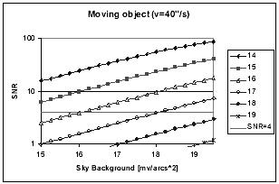 Fig. 5. SNR for objects of various magnitudes crossing the FOV with 40”/s as function
of the background signal.
If we assume a typical object velocity of 40 “/s, the minimal reacquisition time of a
given field is 211 s for the 4.7° FOV to have the survey leak-proof. As this is a very short
reacquisition time, some ways must be found to deal with this requirement. There are several
options: first, we may limit the length of the surveyed stripe in right ascension. Second, the
detector readout may be accelerated by using frame-transfer CCDs and read out to multiple
channels at high frequencies. Third, the slew rate of the telescope must be high, while the
settling time should be kept short. Finally, the number of exposures forming a series may be
minimized.
The analysis of the achievable reacquisition time made clear that for the aimed coverage
of 120° in right ascension with 4 consecutive exposures per field a comparatively high
readout frequency of 5 MHz through 4 channels is needed. With a relaxed readout frequency
of 2 MHz, only 100° in longitude can be covered and only if 3 exposures per series are
sufficient. With 1 MHz readout frequency only 80° in longitude are covered if a series
consists of only 2 exposures, which is not acceptable. On the other hand, if the survey is
limited to 80° in longitude, a wide range of combinations of readout frequencies and number
of exposures per series is possible. From 1 MHz with 2 exposures up to 5 MHz with 4
exposures, everything is possible. There is even some margin left.
3.2.2 Tasking sensors The performance analysis of the 0.5 m GEO tasking sensor showed that the detection of
17 mag objects is possible even under non-optimal observation conditions [6]. The apparent
object brightness of 17 mag corresponds to an object diameter of 1 m observed under a phase
angle of 90°. Using ephemeris tracking, 1 m objects may be observed under less favourable
phase angles.
3.3 Coverage of reference populationThe estimation of the coverage of a MEO reference population by the proposed space
surveillance strategy is ongoing work and therefore not presented here. The minimal
detectable object diameter and the coverage of a reference population are to come.
4 CATALOGUING ALGORITHM VALIDATIONAIUB validated the performance of the algorithms developed to build up and maintain a
catalogue of orbital elements using observations from GEO surveys conducted with ESA’s
Space Debris Telescope at Tenerife, Spain. This validation involved the prototype
implementation of modules for the correlation of observations with a catalogue and the
scheduling of observations to maintain this catalogue using the On-Line Data Processing
System (ODPS). The ODPS is used by AIUB on a routine basis for the ESA surveys; its core
functionalities are presented in [11].
The proposed combined survey and tasking approach, for both GEO and MEO space
surveillance systems, will allow the use of identical algorithms. As such the results of the
algorithm validation are applicable to GEO and MEO with the exception that the frequencies
for tasking observations needed to secure the orbits of newly detected objects differ. A
previous paper [8] presented a method to determine those ‘follow-up’ observation frequencies
for objects in the GEO using the CelMech software [2] for the orbit determination
implemented in the correlation procedures. The estimated MEO tasking frequencies will be
presented in a later paper.
4.1 Catalogue CorrelationComparing the determined orbital elements and positions with propagated elements and
positions from each object in the catalogue is a typical approach to correlate objects with a
catalogue. These correlation algorithms using orbital elements may fail sometimes, if several
candidate catalogue objects have very similar orbits (e.g. in clusters of co-located satellites),
due to unavoidable inaccuracies of the elements in the available catalogue. To circumvent
this, we introduced in our algorithms as a second selection criterion the quality of the orbit
determination using the new observations.
This second step will be carried out for a list of so-called candidate objects that is
obtained from the orbital elements comparison step. For all candidates, all past observations
of the candidate are merged with the new observations. Using the merged observations, the
best fitting orbit is determined. For an orbit determination resulting in a root mean square
(RMS) error smaller than about twice the pointing accuracy, the correlation is considered
successful.
The catalogue correlation algorithm was successfully tested with observations from the
ESASDT on Tenerife. Even objects of clusters could be distinguished (see [6] or [9] for examples).
4.2 Catalogue MaintenanceThe catalogue maintenance is based on two different catalogues, a main catalogue for the
objects with “secured” orbits (accuracy and covered observation duration meet the
requirements), and a temporary catalogue for the other objects.
While the public main catalogue contains only the secured orbits, the temporary
catalogue is only used internally during the acquisition of a secured orbit.
The proposed system infrastructure allows storing both catalogues at a processing
centre, where also the correlation will be performed. This processing centre is responsible for
the planning of the survey and tasking observations, and for the data distribution.
5 CONCLUSION AND OUTLOOKThis paper outlines the key points of a proposal for the optical part of a future European space
surveillance system. The entire space surveillance system proposal was developed in the
context of ESA funded studies lead by ONERA. AIUB was and is involved in the
development of the optical part of this system that is intended to observe the GEO and MEO
region. We showed that the optical system proposal is technically feasible and that a sufficient
performance is expected for the GEO part. The performance analysis of the MEO part is not
yet completed.
The space surveillance strategy is combining survey and tasking observations for both,
MEO and GEO. For the GEO, a so-called ‘stripe’ with a ‘height’ of 34° in declination and a
‘width’ of a few degrees shall be scanned within 8 days. This strategy allows for a leak-proof
survey of the GEO region.
Tasking observations are required to secure the orbits of newly detected objects and to
allow the space surveillance system to provide additional services like dedicated observations
for conjunction analysis.
The proposal for the GEO space surveillance system architecture requires four sensor
sites, each equipped with one 0.5 m telescope dedicated to survey and one 0.5 m telescope for
tasking. Redundancy may require additional telescopes. Tenerife, Cyprus, Perth and the
Marquesas Islands were selected as potential sites. Possibly, already existing sensors such as
the 1 m ESA Space Debris Telescope at Tenerife or AIUB’s 1 m multi-purpose system
ZIMLAT near Bern may contribute as tasking sensors, even though these telescopes are not
optimally suited for survey tasks. The minimal detectable object diameter is 1 m in the worst
case. The presented survey strategy covers over 95% of a reference population
(USSTRATCOM catalogue).
For the MEO survey the system shall continuously scan a right ascension ‘stripe’ at
0° declination. It is possible to limit the system to 2 sites, spaced by about 90° in longitude.
Two dedicated survey sensors (0.8 m f/1 telescopes with 4.7° FOV equipped with a 4k*4k
CCD that allow fast readout through multiple channels) are required, preferably co-located at
proposed GEO sites. The MEO space surveillance system may re-use the GEO tasking
network.
Algorithms for correlating new observations with a catalogue and for the catalogue
maintenance have been presented. These algorithms were successfully validated using
observations of GEO objects from the ESA Space Debris telescope in Tenerife.
The next steps in the development of an independent European space surveillance
system have been recommended in the final report of the study [3]. In this report, solutions for
near-term and far-term systems were presented. Also the use of existing systems for limited
space surveillance activities has been discussed.
The further development of the optical part of a future space surveillance system
requires the set-up of experimental hardware, software and infrastructure in order to gain first
experiences in the field of operational space surveillance.
Acknowledgements. A considerable part of this work was done under ESA/ESOC contracts
16407/02/D/HK and 18574/04/D/HK.
REFERENCES
Размещен 28 ноября 2006
| |||||||||||||||||||||||
|
|
|
|
|
|
|
|