Proceedings of the Fourth European Conference on Space Debris, Darmstadt, Germany, 18-20 April 2005 (ESA SP-587, August 2005)
V. Agapov(1), V. Biryukov(2), R. Kiladze(3), I. Molotov(4), V. Rumyantsev(5), A. Sochilina(6), V. Titenko(7)
(1) Keldysh Institute of Applied Mathematics, Miusskaya Sq., 4, Moscow, Russia, 125047 Space Informatics and Analytical Systems (KIA Systems JSC), Gzhelsky Lane, 20, Moscow, Russia, 107120
Email: avm@kiam1.rssi.ru
(2) Crimean Astrophysical Observatory, Nauchny, Crimea, Ukraine, 98409
Crimean Laboratory of Sternberg Astronomical Institute of Moscow State
University, Nauchny, Crimea, Ukraine, 98409
Email: biryukov@crao.crimea.ua
(3) Abastumani Astrophysical Observatory of the Georgian Academy of Sciences, Kazbegi 2a, Tbilisi, 99532, Georgia
Email: roki@mail.ge
(4) Central (Pulkovo) Astronomical Observatory, Pulkovskoe chaussee, 65/1, St.Petersburg, Russia, 196140 Keldysh Institute of Applied Mathematics, Miusskaya Sq., 4, Moscow, Russia, 125047
Email: molotov@kiam1.rssi.ru
(7) Keldysh Institute of Applied Mathematics, Miusskaya Sq., 4, Moscow, Russia, 125047
Email: optical@kiam1.rssi.ru
ABSTRACT
Under order of the Rusian Academy of Sciences' Center on collection, processing and analysis of information on space debris operated at the Keldysh Institute of Applied Mathematics (KIAM) the group of the researchers developed the program of search, tracking and analysis of orbital evolution of faint objects of space debris in geostationary region (GEO) presumably appeared in events of fragmentation of some resident GEO objects.
Search fields were calculated with usage of the various approaches, each of which is briefly described in the given paper. The search in the calculated fields and their vicinities was carried out within several clear nights in October - December, 2004 and January, 2005. Several faint objects were discovered. These objects were detected repeatedly at the nearest possibility (sometimes in 2-3 weeks of an interruption in observations because of a bad weather). All detected objects were tracked continuously during several subsequent nights. Achieved accuracy of astrometric positions (σ=1") has allowed not only to construct accurate orbits but also to improve estimation of solar radiation pressure coefficient value for each object. It was revealed that at least for 2 objects the solar radiation pressure is the very essential factor causing strong evolution of eccentricity of object's orbit. The further analysis has shown, that the eccentricity of one of objects changes in 5 times during just one half-year. The detail results of researches are presented at this paper. The work is carried out at partial support of the grant INTAS 2001-0669.
1. INTRODUCTION
Center on collection, processing and analysis of information on space debris of the Russian Academy of Sciences (RAS) developed and operated on the basis of the Ballistic Center at the Keldysh Institute of Applied Mathematics (KIAM) carries out works aimed to systematic research of a population of small-sized high altitude objects and their properties. Under order of the Center the group of the researchers from KIAM, Central (Pulkovo) astronomical observatory of the RAS and Crimean astrophysical observatory (CrAO, Nauchny, Ukraine) the special program of search, tracking and analysis of orbital evolution of faint (fainter than 15m) objects in geostationary region (GEO). The program is aimed on reaching of the following purposes:
Improvement of application of the various
methodical approaches of calculation of observation
fields for search of objects in GEO region
Detection of faint objects in GEO region
Tracking of the detected objects
Determination of trajectory parameters and analysis
of orbital elements evolution
Estimation of area-to-mass ratio value for tracked
objects
General statement of the task, processing of measurements, analysis orbital evolution, estimation of area-to-mass ratio values, calculation of ephemeredes for observations and interpretation of results were carried out by the KIAM team. The Pulkovo
observatory team was responsible for the calculation of fields for search of fragments produced in result of supposed explosions, independent analysis of measurements for increase of reliability of results and also for identification of observed objects with probable "parent body". The CrAO team performed search of faint objects in the calculated fields using the selected strategy of objects search, repeated detection and tracking of the rediscovered objects, implemented the techniques of processing of CCD-frames obtained with integration time up to 20 sec.
After obtaining of the first results the research group has addressed to some observatories with the request for scheduling and realization of several sessions of follow-up observations with the purpose of confirmation of results reliability. Observations were carried out at Mondy (Sayan observatory of the Institute of Solar-Terrestrial Physics of the Siberian Department of the RAS), Zimmerwald (Astronomical Institute of University of Bern), PIMS (Observatory Sciences Ltd.) and Xinglong (China) observatories.
On the basis of the obtained sets of astrometric positions the KIAM team is carried out the precise determination of orbit parameters, researched orbital evolution, obtained the estimation of the area-to-mass ratio value, carried out studying of series of measured values of a visual magnitude of objects.
The given work is further development of regularly spent the IADC GEO survey campaigns and its results are essential addition to understanding of real properties of a population of objects of space debris in GEO region.
2. OBSERVATION TOOLS
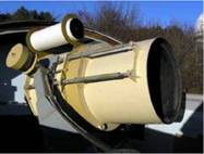
The main tool at realization of observation program is the AT-64 telescope (D = 64 cm, F = 90 cm), established in the CrAO. The telescope is equipped with the ST-8 (KAF-1600) CCD-matrix. The field of view with the given CCD-matrix makes 53x34 arcmin. Limiting magnitude of the instrument is 20m in integral light at the integration time of 120 sec. This mode of observation can be used for search of asteroids. For Earth-orbiting objects of space debris in GEO region limiting magnitude is 17,5m-18m with integration time of 15 sec. The given telescope permits the tracking of objects having angular rate up to 4 arcmin per sec. The exterior of a telescope is shown on Fig.1.
Figure 1. The "-64 telescope at CrAO
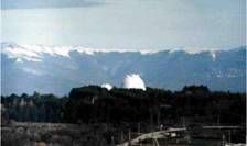
Since March, 2005 usage of the second telescope for observations of small-sized high altitude objects - ZTSh (D = 260 cm, F = 1000 cm) also established in CrAO is started. CCD-matrix IMG-1001E (KAF-1001E) was specially purchased and installed at the given telescope to provide support within frame of the described observation program developed under the order of the Center at KIAM. The field of view is 8.5x8.5 arcmin. Since the telescope has not yet capability of auto tracking of fragments of space debris (the necessary adaptations are carried out) the observations implements with a fixed telescope with periodic manual repositioning at the time of exit of observable object on boundary of a field of view. The exterior of the telescope site is shown in a Fig. 2.
Figure 2. ZTSh telescope site at CrAO
A Zeiss-600 telescope equipped with SIC (Electron) CCD-matrix of 1024x1024 pixels in size was used for observations in Sayan observatory. The field of view is 7.5x7.5 arcmin, limiting magnitude - 18m.
Observations at Zimmerwald observatory were carried out with Im-class telescope equipped with 2048x2048 pixels CCD-matrix. The field of view is 20x20 arcmin, limiting magnitude - 19m.
PIMS observatories are equipped with 40 cm aperture robotic telescopes having CCD-matrix of 1024x1024 pixels in size installed. The field of view is 40x40 arcmin, limiting magnitude - 17m.
Xinlong observatory has used a 60/90 Schmidt telescope with Ford 2048x2048 CCD-matrix. Field of view of the instrument is 58*58 arcmin.
3. OBSERVATION STRATEGIES AND CCD-IMAGES PROCESSING
3.1. Observation strategies
One of key elements of this work is the observation strategy definition from the point of view of two aspects: search of new and repeated detection of earlier observed objects.
One of the approaches used for search of new objects in GEO area is well known. It widely practices at realization of the coordinated IADC GEO survey campaigns. According to the IADC WG1 recommendations the strategy in this case is to point the telescope to a given right ascension (RA) and Declination (DECL) and then take images as quickly as
possible. Thus the effective limiting detectable size is constant for each night. The sky coverage is continuous within each declination band so there are no gaps. This search fence is solid in RA (east-west direction), but leaky in DECL (north-south direction). All of the data is then collected at the same solar phase angle. There is no time lost due to telescope motion. To provide optimal observation conditions search fields are placed close to antisolar point (i.e. to the point with minimal phase angle that as a rule corresponds to maximal brightness of searched object) taking into account that it should be avoid of shadow of the Earth covering some part of GEO region during the period close to spring and autumn equinoxes. Moreover search fields sometimes are placed at areas where the apparent density of the catalogued GEO objects in the RA-DECL-space is maximal.
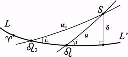
The second approach is developed specially for search of fragments of supposed explosions of some resident GEO objects. The developed theory of evolution of geostationary satellites orbits (Kiladze et al., 2003) allows determining RAAN (Ω) and inclination (i) for all simulated explosion fragments with high accuracy on intervals of 40-50 years. Calculating RA (α) and DECL (δ) for cross points S of orbits of fragments with orbit of the exploded parent satellite on long time frames, it is possible to determine geocentric coordinates of the parent object orbit's segment on which cross points with orbits of all fragments are distributed with a minimum dispersion (Socnilina et al., 2003). Fig. 3 demonstrates geometry of the discussed case.
As the planes of orbits of considered object and its fragments are intersected in two points, the coordinates on cross points S will differ on 180° in α. The value of δ will have the inverse sign.
Figure 3. Geometry of relative position of orbits of a parent satellite and a fragment of its explosion
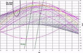
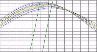
Results of simulation for supposed fragmentations of some Transtage-type and Ekran-type objects are presented at Fig. 4. Tiny blue dots represent trajectories of catalogued GEO objects in geocentric RA-DECL-space as of Feb 09, 2005. Green lines represent conditional boundaries of the galactic equator and solid black line represents the Earth shadow boundary. Magenta and yellow solid lines represent trajectories of supposedly exploded 'parent' objects. Solid circles on these trajectories mark segments where cross points with orbits of all simulated fragments are distributed with a minimum dispersion.
Figure 4. Position of segments of cross points of orbits of fragments with orbit of some supposedly exploded parent objects where cross points distribution dispersion is minimal as of Feb 09, 2005. Transtage-type parent object orbits are shown in magenta, Ekran-type parent object orbits are shown in yellow.
Fig. 5 represents more detailed picture of simulation results for the case of the 1979-078A object (an Ekran-type spacecraft). Only galactic equator boundaries, the Ekran and its simulated fragments trajectories are shown as of Feb 09, 2005. It is clearly visible that the cross points are dispersed along the Ekran trajectory but concentrated in some limited segment. Accordingly, field for search of the Ekran possible explosion fragments can be placed inside of this segment.
Figure 5. Trajectories of Ekran 1979-087A satellite and its explosion fragments as of Feb 09, 2005.
For repeated observation of the earlier detected objects the planar along-trajectory search strategy was realized. While using this strategy it is important to properly estimate an error of object predicted position. If the error is insignificant in comparison with the size of a field of view of the telescope, the object at once falls in a field of view and the special search is not required. Otherwise it is necessary to conduct search. As a rule, for the newly detected objects optically observed on a short time interval, an ellipse of errors of the predicted position has strongly prolate form, thus its semimajor axis is oriented approximately in parallel to trajectory of object motion. It allows to use a simple way of search -"waiting in a point ". Let predicted right ascension and declination of object in the moment t are α and δ respectively. The method of search consists in
observation of a point with coordinates (α,δ) during time interval from t-ΔΤ up to t+ΔΤ, where ΔΤ - some value. Actually the object passes right ascension α in some moment t+εt, and its declination in this moment is equal to δ+εδ. Here εt is an error of the prediction in time, εδ is an error of the prediction in declination. If ΔΤ > 3σ(εt) and fδ/2 > 3σ(εδ), where fδ - size of a field of view on declination, σ(εt), σ(εδ) - RMS values of an error of the object position prediction on time and on declination accordingly, than by search the object will get in a field of view with probability not less than 0.994.
By numerical simulation the RMS values following kinds of errors of the object position prediction are determined: angular position error σ(r), error of the prediction in time σ(εt) and error of the prediction in declination σ(εδ). Angular position error here is understood as angular distance between a predicted and actual position of object. The simulation was made in the following suppositions. Geostationary object is observed on time interval Tobs, during which the angular measurements at regular intervals hm are made, the RMS error of measurements is equal am. Based on the obtained measurements, orbit is determined and then the prediction of a visible position of object for the moment, spaced from the end of an interval of observation by time Tpr is calculated.
Table 1 contains the results of calculations for the case am= 1 arcsec, hm= 1 min and various values of Tobs, Tpr. Object orbit is assumed circular with a semimajor axis of 42164 km and inclination 13°. Observation facility assumed located at 40° latitude.
Table 1. Simulated prediction errors in position of newly detected object. Facility at 40° latitude.
σm, arcsec
hm, min
Tobs
Tpr
σ(r), deg
σ(εt), min
σ(εδ), deg
1
1
10m
30m
0.015
0.07
0.012
1
1
10m
Ih
0.07
0.32
0.04
1
1
10m
2h
0.045
1.9
0.15
1
1
10m
4h
3.2
13
0.5
1
1
10m
Id
40
160
0.5
1
1
30m
2h
0.04
0.17
0.01
1
1
30m
4h
0.25
1.0
0.04
1
1
30m
Id
6.9
28
0.22
1
1
Ih
4h
0.05
0.2
0.007
1
1
Ih
Id
1.2
5.0
0.05
1
1
2h
Id
0.19
0.8
0.05
1
1
2h
lOd
1.9
7.7
0.05
1
1
4h
Id
0.025
0.1
0.0004
1
1
4h
lOd
0.25
1.0
0.003
Depending on selection of orbit parameters of object and coordinates of observation facility the different values of errors are obtained. In particular, the errors of the object position prediction are essentially increased, if the observation facility is located close to orbital plane of the object. Table 2 contains the similar
calculation results as the table 1 does for orbit with an inclination 0° and observation facility located exactly on equator.
Table 2. Simulated prediction errors in position of newly detected object. Facility at 0° latitude.
σm, arcsec
hm, min
Tobs
Tpr
σ(r), deg
σ(εt), min
σ(εδ), deg
1
1
10m
30m
0.13
0.5
0.01
1
1
30m
2h
0.21
0.85
0.0007
1
1
Ih
4h
0.15
0.6
0.0004
1
1
Ih
Id
3.6
14.5
0.0004
1
1
2h
Id
0.34
1.4
0.0002
1
1
4h
Id
0.03
0.12
0.0001
3.2. CCD images processing
Since the purpose of the work was observation of faint objects, for obtaining the image of a moving object on the star background with the help of used on a telescope AT-64 CCD-matrix it is necessary to increase an exposure time. In this case stars looks like points and object looks like a trail. The problem of accurate estimation of astrometric properties of trail objects from single observation is important for predicting its positions at the next time observation. It is necessary for increase of probability of repeated detection of object. To solve the problem some limited estimates based on Cramer-Rao theorem about minimum variance bound are used in processing algorithm.
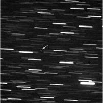
Another situation takes place when telescope control system permits to trace object of interest in case it's predetermined trajectory is known. In that case stars smear to trails on the "moving frame" associated with the moving object. Then the problem is to precisely estimate the CCD-frame position relative same star-trails and calculate coordinates of the point-like (or slightly smear) object on the CCD-frame. Fig. 6 shows an example of CCD-frame obtained in tracking mode of one of discovered objects. High density of stars is clearly visible.
Figure 6. CCD-frame containing the 90008 object image.
Hough transform technique is used for processing of such images in case of absence of a-priory information about star trails direction and length. But usually telescope control system provides such information. In this case cross correlation algorithms are used for star trails selection and their characteristics estimation. Finally more precise estimations of star positions are obtaining with assumption the track is a pixel detector image of segment blurred by 2-D Gauss point spread function (PSF). The finite size of the pixels takes into account, then model image is calculating and PSF is integrating inside of each pixel by analytical calculation. Parameters of the model are estimated with maximum likelihood method. The combination of approximate, heuristic methods and algorithms on the initial stage of processing and more exact estimation on the final stage allows to achieve good outcomes.
3.3. Positional measurements processing
The refinement of orbit was conducted with usage of numerical motion model, which is taking into account the following essential perturbations:
Earth gravity field (EGM-96 model truncated down
to 16x16)
the Moon gravity (DE-403)
the Sun gravity (DE-403)
direct solar radiation pressure in view of the Earth
shadow passages
The calculation of derivatives in the model of orbit determination implements on analytical relations, the integration of equations of motion implements a modified Runge-Kutta method of the 8-th order (Stepaniants et al., 2000).
Already right at the beginning of activity, in November, 2005, at processing of measurements on two detected in
GEO
even the
to known usual Originally
the middle of October objects rediscovered after a two weeks observation interruption due to weather, there was obvious a following fact. For both objects the RMS value of residuals several times has exceeded expected after refinement of orbit parameters and solar radiation pressure coefficient estimation. The external accuracy of single measurements was rated before on the basis of large statistics accumulated on rather bright unknown objects in GEO region (Agapov et al., 2005). Thus value of solar radiation pressure coefficient has appeared extremely large compared population representatives, supposition was considered that different objects on very close orbits actually were observed. However, further analysis has confirmed the obtained estimations of solar radiation pressure coefficient. So some other explanations have to be found for observed measurements inconsistence. One of possible explanation is that variation of solar radiation pressure coefficient due to complex object tumbling is not taken into account in the motion model.
4. RESULTS
As of Jan 01, 2005 orbits of 8 fragments were studied in details. Obtained orbital parameters are summarized in Table 3. Table 3 also contains values of the standard visual magnitude of objects (mean and 3 sigma RMS value, the values are reduced to distance 37000 km and a phase angle 90°) and obtained estimations of the mass-to-area (m/A) ratio value. The value of standard visual magnitude should be considered as the first order estimation since it was calculated assuming a diffuse Lambertian reflection.
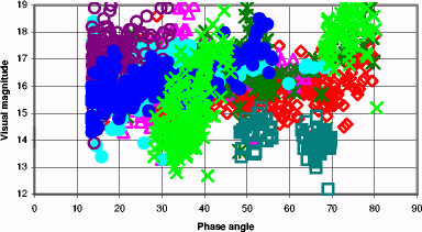
Fig. 7 shows measured values of visible magnitude of all 8 objects in integrated light.
Table 3. Orbital parameters of detected and tracked faint objects
Object
Nignts/ positions
a, km
e
i,°
Ω,°
ω,°
λ, °Ε
unit rate, °/day
Standard visual magnitude
m/A, kg/m2
90003
7/577
40872.0
0.0329
11.37
337.91
343.74
255.94
+17.20
16.91±0.66
0.38-0.43
90004
4/294
43077.2
0.0134
07.40
067.38
018.54
227.93
-11.38
17.56 ±0.99
0.95-3.1
90005
4/158
42015.7
0.0452
14.52
003.25
087.19
162.84
+1.91
17.66 ±0.79
1.55
90006
12/260
42164.9
0.0013
14.69
358.35
007.29
008.83
-0.01
17.53 ±0.74
>100
90007
3/148
41932.6
0.0040
14.54
356.30
246.15
048.79
+2.99
18.36 ±0.86
1.15
90008
4/205
42150.2
0.0045
14.36
003.95
080.84
081.73
+0.18
17.34 ±0.70
>200
95024
2/356
42326.4
0.0234
01.31
069.24
208.94
064.25
-2.01
16.13 ±1.27 18.70 ±0.85
0.9
95029
2/80
42149.6
0.0049
13.62
013.28
260.57
065.07
+0.20
14.77 ±0.58
18
Observed visual magnitude for faint GEO objects O 90003 Δ 90004 Ж 90005 O 90006 O 90007 O 90008 Π 95029 X 95024
Figure 7. Measured visible magnitude in integrated light for 8 faint GEO objects.
The following features of the detected objects are well visible from the given data.
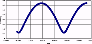
One of objects (90003) has the mass-to-area ratio value only 380-430 g/m2 that is usual for materials used at manufacturing of a multi-layer thermal insulation of spacecrafts. As a result its orbit experiences strong disturbances on the part of direct solar radiation. Fig. 8 shows evolution of an eccentricity of object 90003. It is clearly visible, that all for 7 months its value changes in 5.9 times. Thus the maximum orbital altitude changes more than on 2500 km (from 35000 up to 37550 km). Eccentricity changes due to direct solar radiation pressure influence with period approximately one year. During this period the object reaches protected region of functioning GEO spacecrafts (altitude of 36600 km), within 7.5 months intersects this region and then for 6 months again leave the protected region.
Figure 8. Eccentricity evolution for object 90003.
The second interesting feature of object 90003 is the absence of the obviously expressed relation of a brightness from value of a phase angle in range of phase angles 12°-80°. This results rather unexpected, which requires close detail learning. For object 95024 the strong variability of brightness is visible at different phase angles as well as relation of brightness to value of a phase angle. Such behavior is characteristic for objects such as a plate, flat cover etc.
5. CONCLUSIONS
The results of the carried out researches of faint objects in GEO area have allowed to reveal a number of features of such objects. In particular, the objects with a small mass-to-area ratio value are discovered. It
confirms a stated earlier hypothesis about an incorrectness of the supposition about a zero eccentricity at statistical processing of measurements obtained within the framework of the IADC GEO survey campaigns. Direct solar radiation pressure have the essential influence on orbit evolution for these objects. In view of fast changes of eccentricity and argument of perigee of such objects the statistical samplings of measurements obtained on various night even with a difference of a few months, can contain measurements on the same object, which eccentricity of orbit has undergone significant change. The result of calculation of general quantity of objects in such sampling can appear uncertain, if the changes of eccentricity will not be taken into account. Some of objects have not the obviously expressed relation of value of a brightness to a phase angle in range of phase angles 12°-80°.
The obtained results can be used for refinement of models of a density function of objects in GEO region, and also can serve as a starting point for organization of constant monitoring of GEO region with the purpose of obtaining the maximum reliable information about a true population of objects in it.
The authors would like to acknowledge James Dick, Phil Herridge, Thomas Schildknecht, Zhou Xu, Pavel Papushev, Oksana Yurysheva for the rendered support in realization of additional observation on the detected objects. The work is carried out at partial support of the grant INTAS 2001-0669.
6. REFERENCES
Agapov V., Khutorovsky Z., Boykov V., Sbytov N., Samotokhin A., Experience Of Formation Of The GEO Orbital Information Archive Based On Different Data Sources, Proceedings of the 5th US-Russian Space Surveillance Workshop, 24-27.09.2003, Pulkovo, St. Petersburg, Russia
Agapov V., Dick J., Guseva I., Herridge P., Khutorovskiy Z., Molotov I., Ploner M., Rumyantsev V., Schildknecht T., Stepanyants V., Sukhov P., Titenko V., Joint RAS/PIMS/AIUB GEO survey results. 4th European Conference on Space Debris, ESOC, Darmstadt, 18-20 April, 2005.
Kiladze, R.L, Sochilina, A.S.. On the new theory of Geostationary satellite motion. Astronomical and Astrophysical Transactions, Vol. 22, Nos. 4-5, August-October 2003, pp. 525-528.
Schildknecht T., Musci R., Ploner M., Preisig S., Cruz J. de Leon, Krag H., Optical Observations of Space Debris in the Geostationary Ring, Proceedings of the 3rd European Conference on Space Debris, ESOC, Darmstadt, 19-21 March 2001, SP-473, Vol.1, October 2001
Sochilina A., Kiladze R., On orbital evolution of fragments of exploded objects. Izvestiya GAO at Pulkovo, № 216, 2003, pp.437-438 (rus.)